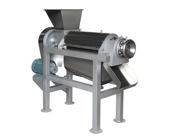
What is the working principle of stainless steel screw Juice
Time:2021-04-08 09:29 Browse:277
1) Working process. Firstly, the power is input by the power part, and the extrusion torque is transmitted from the gear 7 to drive the whole extrusion screw roll 4 to rotate in the direction shown in the figure, and there is a gap between the extrusion cylinder 2 and the extrusion screw roll 4, so it does not roll with it; then the raw material is continuously put into the feed 1; the raw material enters the barrel, and is continuously pushed to the left under the action of the screw roll 4, and the cross-sectional area is continuously reduced from A1 to A3, which is 0 in the limit state, so the extrusion is realized; The residue and juice gradually separated from the juice at 5 points, and finally the residue 6 was discharged at the left end of the extrusion cylinder 2, and the juice flowed out with the surface of the extrusion cylinder 2. Where A3 / A1 = slag rate (slag rate + juicing rate = 100%).
2) Extrusion cylinder follow-up control. In the extrusion process, the extrusion cylinder 2 is designed to move laterally to the left and right, mainly considering that the instability of raw material juice content or the change of slag yield / juice yield (e.g. sugarcane with different sugar content or different parts of sugarcane, etc.) in the process of juicing will cause great changes in the force among the screw roller, extrusion cylinder and raw materials, resulting in waste of success rate and high slag yield. By adding a follow-up block 8 and an extrusion cylinder 2, a spring 9 and a hydraulic cylinder 10, the transverse relative position of the extrusion cylinder 2 and the extrusion spiral roller 4 can be timely adjusted according to different raw materials and slag yield in the juicing process of the extrusion cylinder 2, so as to better control the slag yield and extrusion force and improve the work efficiency. Its essence is to make the cross-sectional area A3 adjustable by controlling the ratio of A3 and A1, that is, the slag yield.
3) Spiral roller cone guide. Between A1 and A3, a spiral guide structure is added to the conical surface at the right end of the extrusion spiral roller 4, which is no longer a common smooth conical surface; while the cross-sectional area of the raw material changes gradually, the guide residue moves to the right along with the spiral groove until the right end of the extrusion cylinder 2 leaves, realizing the slag discharge 6. Avoid the residue stay in the gap of the roller, wedge tightly, resulting in poor slag.


